How Do Smart Butterfly Valves with Position Feedback and IoT Integration Work in Modern Industrial Systems?
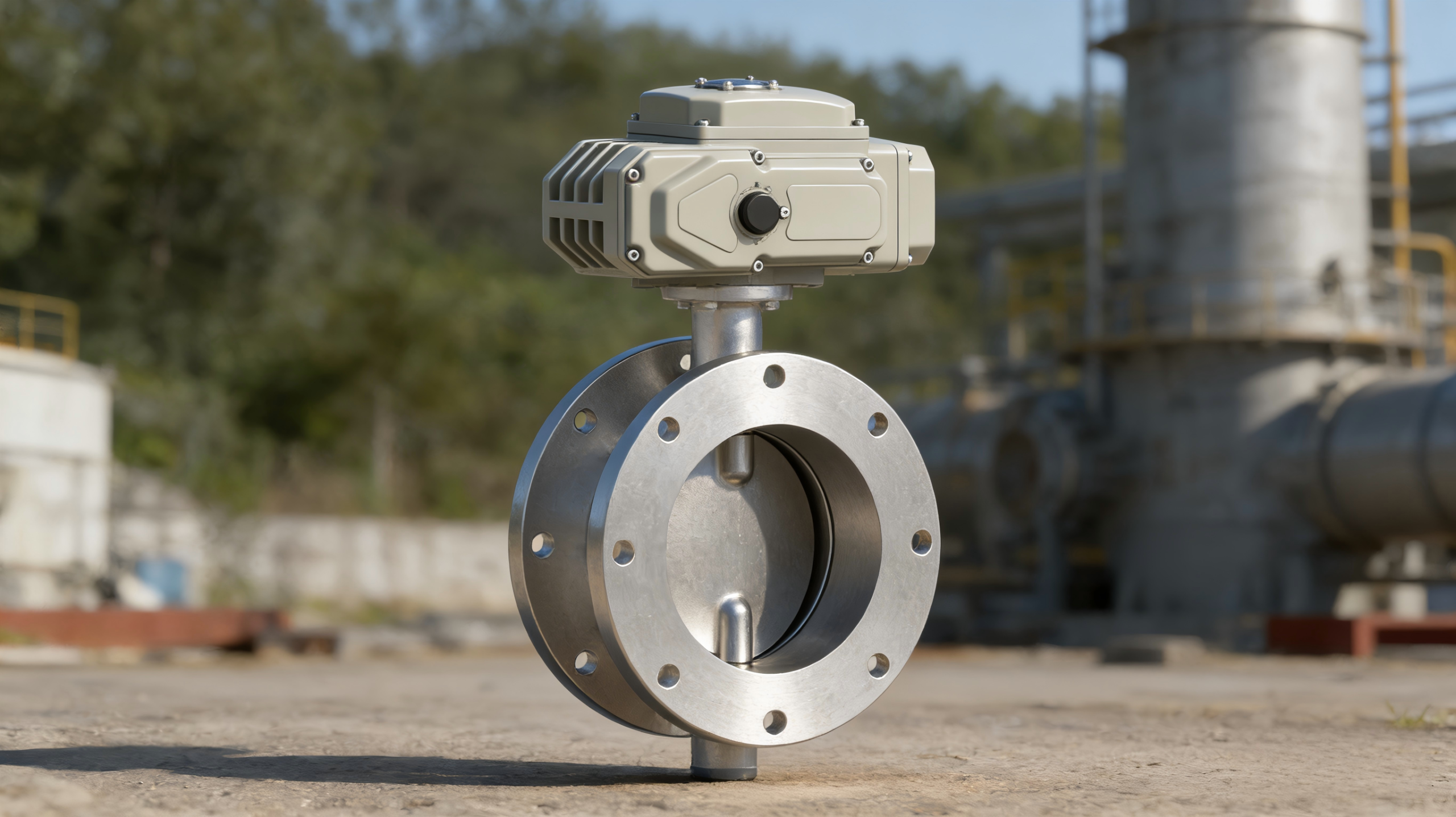
Butterfly valves have long served as standard quarter-turn flow control devices in industrial piping systems. Their compact profile, low weight relative to gate or globe valves, and rapid open-close operation make them practical across a wide range of pipe diameters and pressure classes. In conventional configurations, a butterfly valve consists of a body, a rotating disc, a shaft (stem), and a seat — operated either manually via a lever or gear, or automatically via a pneumatic or electric actuator.
What has changed in recent years is the integration layer built around the valve itself. Smart butterfly valves now incorporate position feedback sensors, embedded diagnostics, and digital communication interfaces that connect directly to SCADA systems, PLCs, or cloud-based IoT platforms. This article examines how these components work, what specifications are relevant, and where this technology applies in process automation environments.
What Makes a Butterfly Valve "Smart"?
A conventional butterfly valve becomes a smart valve when it is equipped with three additional functional layers: real-time position sensing, onboard signal processing, and a digital communication interface. These layers transform a passive mechanical device into an active data-reporting node within an industrial control architecture.
Position Feedback
Position feedback refers to the continuous or discrete measurement of the valve disc's angular position, typically expressed as a percentage of opening (0% = fully closed, 100% = fully open). This feedback is generated by sensors mounted on or integrated into the actuator. Common sensor types include resistive potentiometers, Hall-effect sensors, and magnetostrictive position transducers. The output signal is typically 4–20 mA analog, or digital via protocols such as HART, Modbus RTU, or PROFIBUS.
Embedded Diagnostics
Smart actuators can monitor internal parameters including actuator torque, cycle count, travel time, and motor temperature. Deviations from baseline values can indicate seal wear, mechanical obstruction, or actuator degradation — providing condition data that supports maintenance scheduling without requiring manual inspection.
IoT Connectivity
IoT-enabled butterfly valves transmit operational data beyond the local control loop. Connectivity options include wired fieldbus (Modbus TCP, PROFINET, EtherNet/IP) and wireless protocols (WirelessHART, LoRaWAN, Wi-Fi, or cellular). The data can be consumed by edge gateways, cloud dashboards, or enterprise asset management systems.
Working Principle of a Butterfly Valve with Smart Actuator
The mechanical operation of a smart butterfly valve is identical to any standard butterfly valve. A disc mounted on a central shaft rotates 90° between fully closed and fully open positions. In the closed position, the disc seats against a resilient or metal seat to create a seal. In intermediate positions, the disc partially obstructs the flow path, providing throttling capability with an approximately equal-percentage flow characteristic.
The smart functionality resides in the actuator and its associated electronics. When a control signal is received — for example, a 4–20 mA command from a PLC — the actuator drives the disc to the target position. The position feedback sensor measures the actual disc angle and reports it back to the controller. This closed-loop arrangement allows for continuous modulating control rather than simple on/off operation.
The actuator's onboard processor can also execute local logic — fail-safe positioning (fail-open or fail-close on signal loss), partial stroke testing for safety valves, and alarm generation when operating parameters exceed configured thresholds.
Key Specifications for Smart Butterfly Valves
The following parameters are relevant when evaluating or specifying a smart butterfly valve for process automation. Exact values will vary by manufacturer, model, and application.
Valve Body Specifications
| Valve Type | Wafer, Lug, Double-flanged |
| Nominal Sizes | DN50 – DN1200 (2″ – 48″) |
| Pressure Rating | PN10, PN16, PN25; ASME Class 150/300 |
| Body Material | Ductile iron (GGG40/GGG50), WCB carbon steel, CF8M stainless steel |
| Disc Material | CF8, CF8M, Duplex SS, Nickel alloy (application-dependent) |
| Seat Material | EPDM, NBR, FKM/Viton, PTFE, metal-to-metal (triple eccentric) |
| Design Standard | EN 593, API 609, BS EN 12516 |
| Temperature Range | -29°C to +200°C (resilient seat); up to +425°C (metal seat) |
Smart Actuator & Feedback Specifications
| Actuator Type | Electric (quarter-turn), Pneumatic (scotch-yoke / rack-and-pinion) |
| Control Signal | 4–20 mA, 0–10 V, Digital (HART, Modbus, PROFIBUS) |
| Position Feedback Output | 4–20 mA, 0–10 V, discrete (SPDT contacts), digital bus |
| Position Resolution | ≤ 0.1% (digital), ≤ 1% (analog) |
| Fail-Safe Action | Fail-close, Fail-open, Fail-in-place (configurable) |
| Ingress Protection | IP67, IP68 (submersible options) |
| Explosion Protection | ATEX, IECEx (Zone 1/2, Zone 21/22) |
| Mounting Standard | ISO 5211 |
IoT / Communication Specifications
| Wired Protocols | Modbus RTU/TCP, PROFIBUS DP, PROFINET, EtherNet/IP, HART |
| Wireless Protocols | WirelessHART, LoRaWAN, Wi-Fi, Bluetooth (commissioning) |
| Data Reported | Position %, torque, cycle count, temperature, travel time, alarms |
| Edge Integration | MQTT, OPC UA, HTTP/REST API (via gateway) |
| Power Supply | 24 V DC, 110/220 V AC, or battery / solar (wireless variants) |
Communication Protocols: Wired and Wireless Options
Protocol selection depends on the existing control architecture, required update rate, distance from controller, and hazardous area classification. Below is a summary of the most commonly used protocols for smart valve communication.
Analog signal with digital overlay. Compatible with legacy DCS/PLC systems. Supports up to 256 device variables.
Serial (RS-485) or Ethernet. Widely adopted, simple register-based polling. Suitable for most SCADA environments.
Deterministic fieldbus / industrial Ethernet. Common in Siemens-based automation architectures. Supports cyclic and acyclic data.
Lightweight publish-subscribe (MQTT) or unified architecture (OPC UA) for cloud and edge computing integration.
Battery-powered wireless options for remote or retrofit installations. Mesh (WirelessHART) or LPWAN (LoRaWAN) topology.
CIP-based industrial Ethernet. Native to Allen-Bradley / Rockwell ecosystems. Supports implicit (I/O) and explicit (messaging) connections.
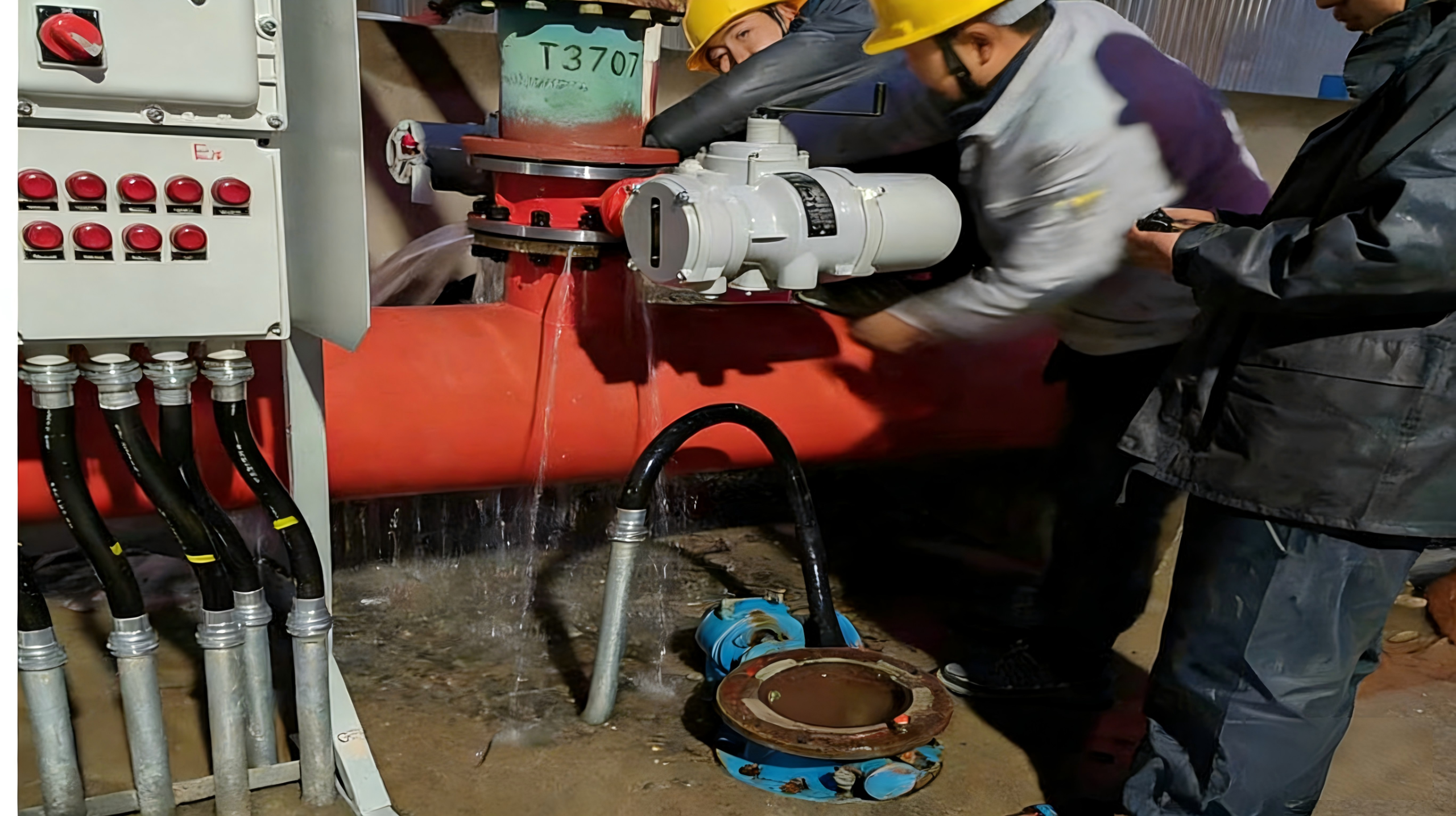
Installation and Commissioning Considerations
Installing a smart butterfly valve follows the same mechanical procedures as a conventional actuated butterfly valve, with additional steps for signal wiring, protocol configuration, and system integration.
- Mechanical mounting: Ensure correct orientation of the disc and shaft relative to the flow direction. For wafer-type valves, use proper flange bolting to avoid seat compression issues. Verify that pipe flanges are aligned and that the valve is not used as a pipe-alignment device.
- Actuator mounting: Follow ISO 5211 interface dimensions. Confirm the actuator torque output exceeds the valve's required breakaway torque, including a safety factor (typically 1.3× to 1.5×).
- Signal wiring: Route 4–20 mA cables separately from power wiring to minimize electromagnetic interference. For HART communication, use shielded twisted-pair cable with a single-point ground.
- Commissioning: Calibrate position feedback zero (fully closed) and span (fully open). Verify fail-safe action by removing the control signal. Perform a stroke test and record travel time as a baseline for future diagnostics.
- IoT gateway setup: For wireless or cloud-connected installations, configure the gateway's device address, polling interval, and data mapping. Verify end-to-end data flow from the valve to the monitoring platform before placing the valve in automatic control.
Industrial Application Scenarios
Smart butterfly valves with position feedback and IoT connectivity are deployed across multiple industrial sectors. The following application contexts represent common configurations.
Water and Wastewater Treatment
Butterfly valves are widely used in treatment plants for flow isolation and throttling in filtration, aeration, and chemical dosing lines. Position feedback enables the control system to verify valve state during automated batch sequences. IoT connectivity allows centralized monitoring of valve health across distributed pump stations and remote treatment facilities.
Chemical and Petrochemical Processing
In chemical plants, butterfly valves handle process fluids, cooling water, and utility lines. Metal-seated triple eccentric butterfly valves are used for higher temperature and pressure services. Smart diagnostics — particularly torque trending and cycle counting — support predictive maintenance in environments where unplanned shutdowns carry high cost.
HVAC and Building Automation
Large commercial HVAC systems use butterfly valves for chilled water and condenser water regulation. BACnet or Modbus-connected smart valves integrate directly into building management systems (BMS), enabling automated seasonal setpoint adjustment and energy usage reporting.
Power Generation
Cooling water intake and discharge systems, steam condensate lines, and fuel gas regulation circuits in power plants use butterfly valves in sizes from DN200 to DN1200+. Position feedback is critical in these applications for compliance with operational safety protocols, and IoT connectivity supports fleet-wide asset performance monitoring.
A New Phenomenon: The Convergence of Valve Hardware and Digital Infrastructure
The consequence for engineers and system integrators is that butterfly valve selection now involves evaluation criteria beyond pressure class, material, and size. Communication protocol compatibility, diagnostic data availability, cybersecurity posture of the device firmware, and total cost of ownership including data infrastructure — these are all now part of the specification process.
Notes, Limitations, and Practical Constraints
- Not all butterfly valves are suitable for modulating control. Concentric (centric) disc designs with resilient seats can exhibit seat wear when held in intermediate positions under high-velocity flow. For throttling service, eccentric or high-performance butterfly valve designs are preferable.
- Wireless latency: LoRaWAN and similar LPWAN protocols have update intervals measured in seconds to minutes. They are suitable for condition monitoring, not closed-loop control. Real-time modulation requires wired signal paths.
- Cybersecurity: Any valve connected to an IP-based network is subject to industrial cybersecurity requirements (IEC 62443). Firmware update capability, role-based access control, and encrypted communication should be verified during procurement.
- Environmental constraints: Smart actuator electronics have operating temperature limits (typically -25°C to +70°C for standard electronics). High-temperature or high-vibration installations may require hardened or remotely mounted electronic enclosures.
- Interoperability: Not all smart actuators support all protocols. Integration with legacy DCS platforms may require protocol converters or gateway hardware, adding cost and potential failure points.
Summary for Technical Decision-Makers
Smart butterfly valves combine the established mechanical simplicity of quarter-turn disc valves with position feedback sensors, onboard diagnostics, and digital communication interfaces. These additions enable closed-loop position control, condition-based maintenance, and integration with IoT and SCADA systems.
The principal specifications to evaluate include: valve body design (wafer, lug, flanged), disc configuration (concentric, double eccentric, triple eccentric), seat material, actuator type (electric or pneumatic), position feedback resolution and output type, supported communication protocols, and environmental ratings (IP, ATEX/IECEx).
This technology is most impactful in installations where manual valve inspection is impractical, where process compliance requires position verification, or where centralized monitoring of distributed valve assets offers operational or maintenance cost reduction.
Protocol selection, cybersecurity, and integration architecture should be addressed early in the engineering phase — these factors are now as important as the traditional mechanical and material specifications.