Butterfly Valve Cv/Kv Sizing: Practical Method for Process Engineers
Selecting a butterfly valve for a process line requires more than matching a pipe size. The flow coefficient — expressed as Cv in imperial units or Kv in metric units — determines whether a valve will deliver the required flow at the available pressure drop. Undersized valves create excessive restriction; oversized valves operate near fully open, reducing controllability and accelerating seat wear.
This article explains the Cv and Kv sizing method for butterfly valves in industrial liquid service: the governing formulas, how valve opening angle affects the coefficient, and the step-by-step process engineers use to reach a working valve selection.
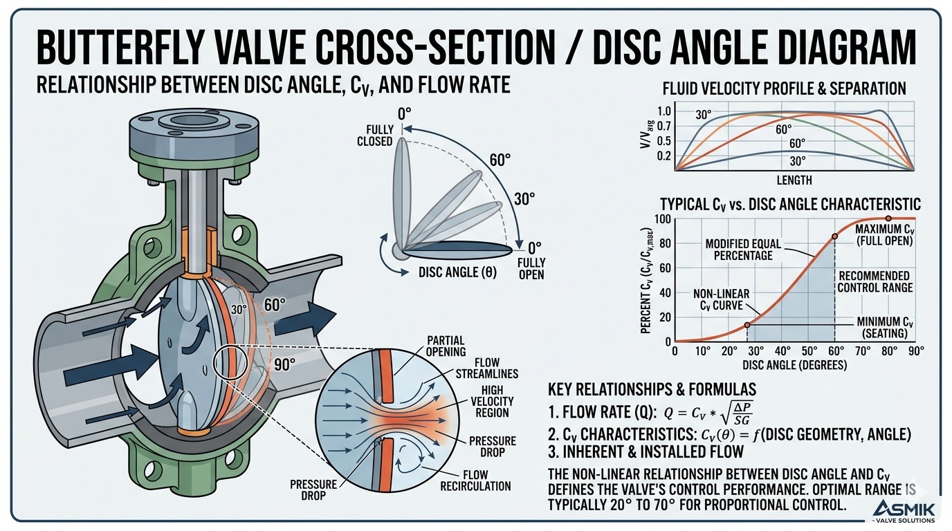 Butterfly valve cross-section showing disc position and flow path
What Are Cv and Kv Flow Coefficients?
The flow coefficient quantifies a valve's capacity to pass fluid under a defined pressure drop. It is an empirically derived value unique to each valve model, size, and disc position.
- Cv is defined as the flow rate in US gallons per minute (GPM) of water at 60 °F that produces a pressure drop of 1 psi across the valve.
- Kv is the metric equivalent: the flow rate in m³/h of water at 16 °C producing a pressure drop of 1 bar.
The two values are related by a fixed conversion:
Butterfly valve manufacturers publish Cv (or Kv) values at multiple disc opening angles — typically from 10° to 90° in 10° increments. The rated full-open Cv is the most commonly referenced figure, but partial-opening values are critical for control valve applications.
Sizing Formula for Liquid Service
For incompressible fluids (liquids), the ISA/IEC standard flow equation used to calculate the required Cv is:
Where:
| Symbol | Parameter | Unit |
|---|---|---|
| Q | Volumetric flow rate | US GPM |
| SG | Specific gravity of fluid (relative to water at 60 °F) | Dimensionless |
| ΔP | Differential pressure across valve | psi |
| Cv | Required flow coefficient | GPM / √psi |
For metric inputs, the equivalent Kv formula is:
How Disc Opening Angle Affects Cv
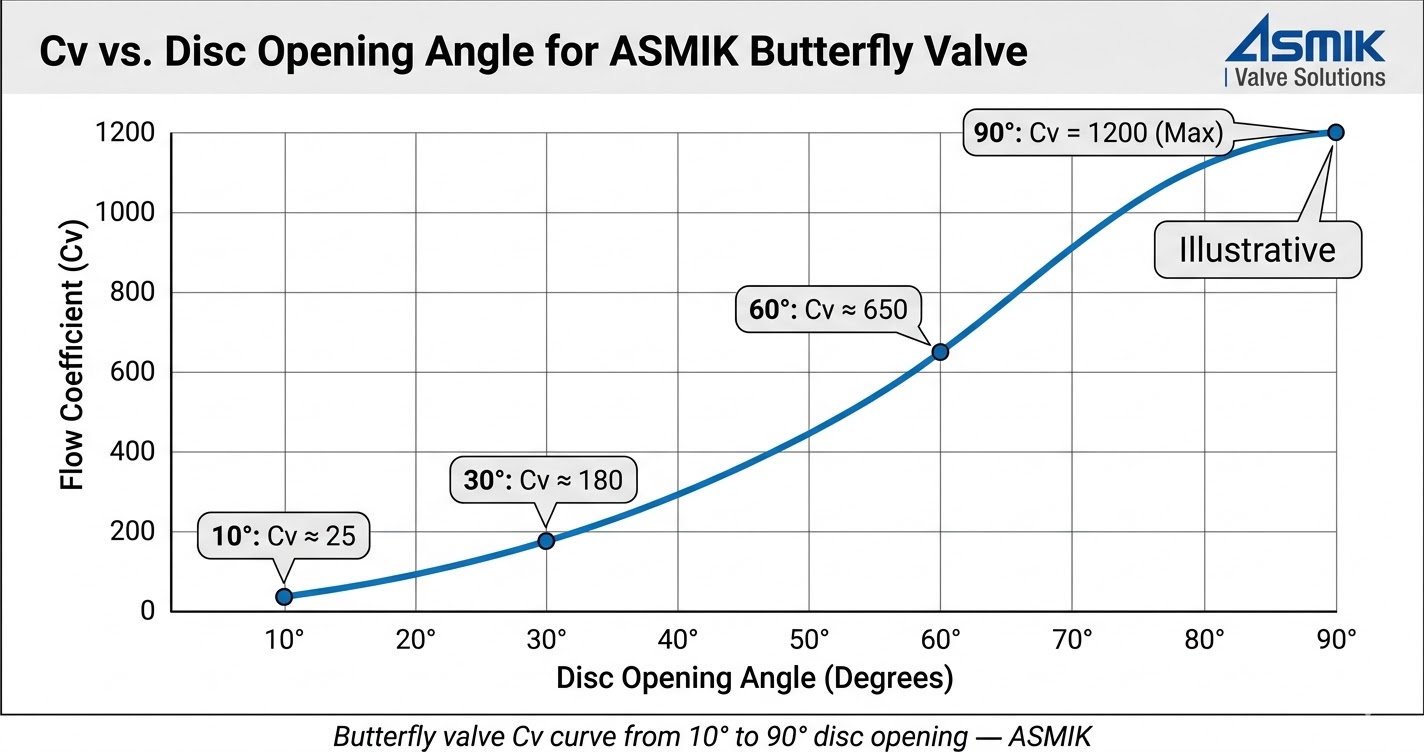 Cv vs. disc opening angle curve for butterfly valve
Unlike a gate valve, which has a near-linear Cv profile at full open, a butterfly valve disc sweeps through a 90° arc. The effective flow area changes non-linearly, so Cv does not scale proportionally with angle.
Key observations from typical Cv-angle data:
- At 10°–20° disc opening, Cv is very low; throttling is possible but flow resolution is coarse.
- The steepest gain in Cv occurs between 40° and 70°, making this the preferred control range.
- Above 70°–75°, Cv approaches full-open values and disc torque increases sharply due to hydrodynamic forces.
- At 90° (full open), the disc is parallel to flow; rated full-open Cv applies.
For control valve sizing, engineers commonly target a normal operating angle of 50°–65°, with the calculated required Cv falling within that angle's published range.
Step-by-Step Sizing Procedure
-
1
Define the design flow conditions. Establish the maximum and normal flow rates (GPM or m³/h), the fluid specific gravity, and the allowable pressure drop across the valve at each condition.
-
2
Select the design pressure drop. For throttling/control service, assign 10–15% of total system ΔP to the valve. For on/off isolation, use the full available differential pressure.
-
3
Calculate the required Cv. Apply the formula: Cv = Q × √(SG / ΔP). This gives the minimum Cv the valve must provide at the design operating point.
-
4
Match to valve Cv table. Consult the manufacturer's Cv-vs-angle table for the valve model and size. Identify the disc angle at which the valve's Cv meets or exceeds the required value.
-
5
Verify the operating angle. Confirm the matched angle falls within the recommended control range (typically 20°–70°). If the required Cv is only met above 75°, the valve is undersized — select the next larger size.
-
6
Check the rangeability. Calculate the ratio of maximum to minimum required Cv. Ensure the valve's Cv range across its controllable angle span covers this ratio without exceeding seat or actuator limitations.
Worked Example
A process line carries water (SG = 1.0) at a maximum flow rate of 200 GPM. The system analysis allocates 8 psi of differential pressure to the control valve.
The engineer consults the manufacturer's Cv table for a candidate 4-inch butterfly valve. If the table shows Cv = 68 at 60° and Cv = 95 at 70°, the required Cv of 70.7 is achieved just above 60° — within the recommended control range. The selection is valid.
If the same required Cv of 70.7 was only met at 80°, the 4-inch valve would be rejected and a 5-inch or 6-inch model evaluated instead.
Pressure Drop Allocation and Cavitation Considerations
Butterfly valves operating with high differential pressure on liquids can enter cavitation if the internal pressure at the vena contracta drops below the fluid's vapor pressure. This is especially relevant in cold-water and low-vapor-pressure liquid services.
Engineers assess cavitation risk using the valve's published cavitation index (Cv-based) or sigma value (σ). When the process ΔP exceeds the threshold for incipient cavitation at the selected angle, options include reducing the assigned pressure drop, selecting a valve with a higher cavitation index, or using a multi-stage pressure drop arrangement.
Summary for Process Engineers
Butterfly valve Cv/Kv sizing is a defined two-step process: calculate the required coefficient from flow rate and pressure drop, then match it to the valve's angle-dependent Cv table at a disc position that supports stable control or full-flow isolation.
Key design checkpoints:
- Target a normal operating angle between 20° and 70° for throttling service.
- Use Cv = Q × √(SG / ΔP) for liquid sizing in imperial units; Kv = Q × √(SG / ΔP) for metric.
- Convert between Cv and Kv using the 1.156 / 0.865 factor.
- Validate against full-open Cv to confirm no pressure deficit at maximum flow.
- Assess cavitation risk when ΔP is high relative to fluid vapor pressure.
Frequently Asked Questions
Need Butterfly Valve Sizing Support?
ASMIK's technical team can assist with Cv/Kv calculations, valve selection, and actuator matching for your process requirements.